Simulated Radio
I worked with two other people to create our own version of an amplitude modulation (AM) radio. We created signal generation, transmitter, and receiver circuits in the simulation software LTspice.
At the highest level, there are two primary components needed for AM modulation – a transmitter and a receiver. The transmitter encodes a message onto a carrier signal of the desired frequency. For the case of AM, the encoding occurs by scaling the amplitude based on the input signal, thus encoding the signal onto the envelope of the signal. This allows for the signal to be sent at a higher frequency. The modulated signal is then received by a receiver after passing through a channel, which can be anything from air to a wire. For this particular implementation, the channel was a simple wire without any loss or added noise. The received signal is then demodulated using an envelope detector which first rectifies the signal and removes the high frequency carrier wave. Our block diagram of our radio can be seen above.
The transmitter is built using an oscillator and multiplier. The output of the oscillator creates a carrier wave to be modulated with a message signal. To get the modulation to occur, namely amplitude modulation, both the carrier and message must be passed into a multiplier. This results in a modulated signal which can be sent over a desired frequency to be received by a receiver, which will demodulate the signal.
To generate oscillations at a fixed frequency, we created a circuit based on the Colpitts oscillator which was invented by Edwin H. Colpitts in 1918. Part of the LC oscillator family, this oscillator uses an inductor (L) and a capacitor (C) of particular values to generate oscillations at our designed frequency.
For the mixer, we implemented two approaches. For our first approach, we used three differential amplifiers to form a Gilbert Cell Mixer. For our second approach we used an operational amplifier to form a Log Anit-Log Mixer.
The receiver, like the transmitter, is built using a few components. In many cases, an antenna or something similar is needed to receive the signal, but for the tests in this paper, the transmitter was connected via a wire. Because an amplitude modulated signal is being received, the envelope of that signal must be extracted to find the original message signal. This is often accomplished by using a rectifier paired with a low pass filter.
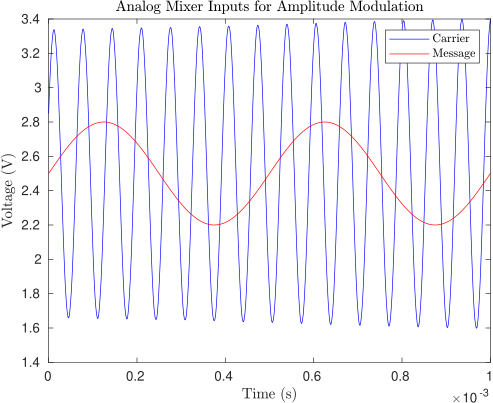
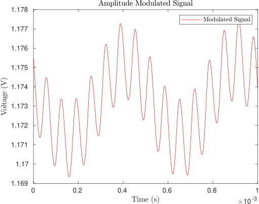
The mixed and transmitted signal for our radio can be seen in the bottom two figures below.
The paper written by me and my partners can be read here
The code can be found on Github

